Filters 2D was a good experiment into shaders land. I joined Da Viking Code in April and one of my main mission was to update this plugin and going deeper in shaders experiments. We’re glad to provide a plugin update with many improvements. Let’s go for some explanations on problems we encounter during the upgrades and fixes.
Float precision on mobile GPU and Desktop GPU

The first thing we worked on was some artefacts display on pixelate, outline and blur filters. This artefacts are saw on mobile devices.
We tested the filters on our mobile devices to determine the cause of this artefacts. We saw the artefacts displayed on some low-middle tier mobile, and top tier had no issues. This artefacts effects are similar of an other artefact knew in light simulation : the acne artefact.
The acne artefact may be cause by a float precision problem. When we worked on extreme precise measure and we apply mathematical operations, it’s possible we reach the float precision limit. The difference between float values become larger then the precision we need. It results a stair effect on compute values and create acne artefact.
In shaders, when we work on pixel, the pixel positions on a texture are between 0 and 1 : {0,0} for the texture origin position and {1,1} for the texture end position.
With a thin range like this, the float precision is crucial. So we mainly focus on this.
After some research, it appears mobile GPUs are unequal in float resolution. Some GPU like the Mali-450 have only 16 bit to encode a float against 32 bit to a desktop GPU. You can found more information about it on the Unity documentation : https://docs.unity3d.com/Manual/SL-DataTypesAndPrecision.html.
During research, we found the works of Tom Olson and Stuart Russell on float precision. https://community.arm.com/graphics/b/blog/posts/benchmarking-floating-point-precision-in-mobile-gpus.
Their work is to determine the number of bit in float which participate on the decimal precision. We adapted their works to use their shader on Unity.
We saw the GPU mali-450 have 10 bit on the 16 bit float for the decimal precision. On a desktop GPU this number is 23.


With this info, we looked for a way to reduce the necessary precision or to bypass the problem.
First, we look to compute the value in the vertex shader, because in the vertex shader the float resolution is more often higher than in the fragment shader. But when we take the texture pixels in the fragment shader to make the effect, the value was redefined with the low resolution.
After, we try to make the effect in the vertex shader (compute values + combine pixels) with no success. It’s not very well supported on shader, only the newest graphic API version allow this functionality. And in the other hand, the graphic API workflow isn’t design to work on pixel elsewhere than in the fragment shader.
So, since the problem can’t be solved in the shaders and bypass the problem, we looked in the other way. The shaders works on the pixel position and with the float precision, the artefacts appears. We looked on the sprites to decide what could be done.
The sprites of our demo were in a atlas of 4096×2048 pixels. It’s a pretty huge atlas, so the pixel size is 1/4096 (2.44*10-4). This need a dawn precision and with the poor float resolution on GPU mobile, it’s not surprising that it cause problems. So, to be sure, we test with a sprite in its source file and no artefacts appears.
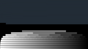
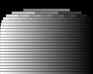
We made a benchmark test scene to observe the consequences of atlas sizes on the filters effect, and decide if reduce the atlas size is a good solution.

Like you can see, the atlas size have a significant impact on the artefacts with a poor float resolution.
So we warn you to use large atlas with caution, especially if you want to use filters on mobiles. At least, on low and medium tier mobile in 2017.
Unity UI mask & stencil buffer
Our filters can be applied on UI elements, but we discovered filters don’t consider none UI mask : 2D rect mask or the standard mask. So we implemented this functionnality.
The 2D rect mask works only on the 2D space {X, Y}, the Z space is ignore.
The 2D rect mask create a rectangle (2 vector2 {X,Y} in a vector4) following the shape of the attached UI GameObject. Then push this rectangle in child GameObject to transfer to their shaders. Here, shaders must compare the world position of their pixel to the rectangle given by the mask, the UnityGet2DClipping() do this job.
Here is the minimum code to use the 2D rect mask on your shaders :
Shader "MyShader"
{
    Properties {
        [PerRendererData]_MainTex_MainTex("Base (RGB)", 2D) = "white" {} // Main texture
    }
    SubShader {
        Tags { ... }

        Cull Off
        Lighting Off
        ZWrite Off
        ZTest [unity_GUIZTestMode]
        Blend SrcAlpha OneMinusSrcAlpha

        Pass {
            CGPROGRAM // Define shader program

            #pragma vertex vert     // Specify vertex shader function called vert
            #pragma fragment frag   // Specify fragment shader function called frag
            #pragma multi_compile __ UNITY_UI_ALPHACLIP

			#include "UnityCG.cginc"
            #include "UnityUI.cginc" // Import the UnityGet2DClipping funciton

            // Define structure to pass to vertex shader
            struct appdata_t {
                float4 vertex   : POSITION;
                float4 color    : COLOR;
                float2 texcoord : TEXCOORD0;
            };

            // Define structure to pass from vertex shader to fragment shader
            struct v2f {
                half2 texcoord : TEXCOORD0;   // Texture coords given by Unity
                float4 vertex  : SV_POSITION; // Position of the vertex after being transformed into projection space given by Unity
                fixed4 color   : COLOR;       // Vertex color given by Unity
                float4 worldPosition : TEXCOORD1; // The world pixel position for the 2D Rect Mask
            };

            // Get properties of shader
            sampler2D _MainTex;
            float4 _ClipRect; // The 2D rectangle Mask

            // Vertex shader
            v2f vert(appdata_t IN) {
                v2f OUT;
                OUT.worldPosition = IN.vertex;
                OUT.vertex = UnityObjectToClipPos(OUT.worldPosition);

                OUT.texcoord = IN.texcoord;

                OUT.color = IN.color;
                return OUT;
            }

            // Fragment shader to give final color of the pixel
            fixed4 frag(v2f i) : COLOR {
                half4 outputColor = (tex2D(_MainTex, IN.texcoord) * IN.color;
                outputColor.a *= UnityGet2DClipping(IN.worldPosition.xy, _ClipRect);

                #ifdef UNITY_UI_ALPHACLIP
                clip (outputColor.a - 0.001);
                #endif

                return outputColor;
            }
            ENDCG
        } // Pass
    } // SubShader
    Fallback "Sprites/Default"
}
Plus the 2D rect mask, we can use the standard mask. The standard mask use the stencil buffer to perform the mask functionality.

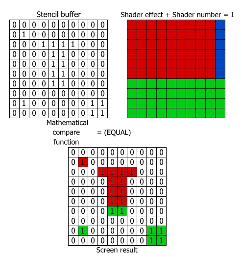
The stencil buffer in shaders used to display or not a texture pixel. It’s more or less a mask function apply after the z-buffer.
It’s composed of a number assigned to the shader, a number store in a buffer readable by all shaders, and a mathematical compare function.
The numbers are between 0-255 and the buffer store a number for each screen pixel like an image.
The program determine on which screen pixel the current pixel texture will be render, and take the stencil buffer number of this screen pixel.
The shader stencil number is compared with the stencil number taken previously. If the mathematical compare is exact (or true), the pixel is display, else it is not.
8 mathematical compare functions exist : Always, Never, Greater, GEqual, Less, LEqual, Equal, and NotEqual.
| Compare function name |
Corresponding number in shaders | Mathematical meanning | Test results |
| Always | 8 | Always exact or true | 0 Always 1 ⇒ √ 0 Always 0 ⇒ √ 1 Always 0 ⇒ √ |
| Never | 1 | Nerver exact or true | 0 Never 1 ⇒ Χ 0 Never 0 ⇒ Χ 1 Never 0 ⇒ Χ |
| Greater | 5 | > | 0 Greater 1 ⇒ Χ 0 Greater 0 ⇒ Χ 1 Greater 0 ⇒ √ |
| GEqual | 7 | >= | 0 GEqual 1 ⇒ Χ 0 GEqual 0 ⇒ √ 1 GEqual 0 ⇒ √ |
| Less | 3 | < | 0 Less 1 ⇒ √ 0 Less 0 ⇒ Χ 1 Less 0 ⇒ Χ |
| LEqual | 4 | <= | 0 LEqual 1 ⇒ √ 0 LEqual 0 ⇒ √ 1 LEqual 0 ⇒ Χ |
| Equal | 3 | = | 0 Equal 1 ⇒ Χ 0 Equal 0 ⇒ √ 1 Equal 0 ⇒ Χ |
| NotEqual | 6 | ≠ | 0 NotEqual 1 ⇒ √ 0 NotEqual 0 ⇒ Χ 1 NotEqual 0 ⇒ √ |
After that, the stencil buffer number could be modified and gave to the next shader.
You can find more information about the stencil buffer in the unity documentation : https://docs.unity3d.com/Manual/SL-Stencil.html.
So in our case, the code to use the stencil buffer is like this :
Shader "MyShader" {
    Properties {
        [PerRendererData]_MainTex_MainTex("Base (RGB)", 2D) = "white" {} // Main texture
        // required for UI.Mask
        _StencilComp ("Stencil Comparison", Float) = 8 // The Mathematical compare function
        _Stencil ("Stencil ID", Float) = 0 // The stencil shader number
    }

    SubShader {
        Tags{
            "Queue"           = "Transparent"
            "IgnoreProjector" = "true"
            "RenderType"      = "Transparent"
            "PreviewType"     = "Plane"
            "CanUseSpriteAtlas"="True"
        }

        // required for UI.Mask
        Stencil {
            Ref [_Stencil] // The stencil shader number
            Comp [_StencilComp] // The Mathematical compare function
        }

        Cull Off
        Lighting Off
        ZWrite Off
        ZTest [unity_GUIZTestMode]
        Blend SrcAlpha OneMinusSrcAlpha

        Pass {
            CGPROGRAM // Define shader program

            #pragma vertex vert     // Specify vertex shader function called vert
            #pragma fragment frag   // Specify fragment shader function called frag

            #include "UnityCG.cginc"

            // Define structure to pass to vertex shader
            struct appdata_t {
                float4 vertex   : POSITION;
                float4 color    : COLOR;
                float2 texcoord : TEXCOORD0;
            };

            // Define structure to pass from vertex shader to fragment shader
            struct v2f {
                half2 texcoord : TEXCOORD0;   // Texture coords given by Unity
                float4 vertex  : SV_POSITION; // Position of the vertex after being transformed into projection space given by Unity
                fixed4 color   : COLOR;       // Vertex color given by Unity
            };

            // Get properties of shader
            sampler2D _MainTex;

            // Vertex shader
            v2f vert(appdata_t IN) { ... }

            // Fragment shader to give final color of the pixel
            fixed4 frag(v2f i) : COLOR { ... }

            ENDCG
        } // Pass
    } // SubShader
    Fallback "Sprites/Default"
}
Conclusion
We didn’t mention all the works done in this update, but we hope you will appreciate the fixes and the new features.
For the next update, what kind of filter effects would you like to see in Filters2D? Or maybe a new feature?
We hope you appreciate this update!
